• ×
    Information
    Windows update impacting certain printer icons and names. Microsoft is working on a solution.
    Click here to learn more
    Information
    Need Windows 11 help?
    Check documents on compatibility, FAQs, upgrade information and available fixes.
    Windows 11 Support Center.
  • post a message
  • ×
    Information
    Windows update impacting certain printer icons and names. Microsoft is working on a solution.
    Click here to learn more
    Information
    Need Windows 11 help?
    Check documents on compatibility, FAQs, upgrade information and available fixes.
    Windows 11 Support Center.
  • post a message
Guidelines
The HP Community is where owners of HP products, like you, volunteer to help each other find solutions.
Archived This topic has been archived. Information and links in this thread may no longer be available or relevant. If you have a question create a new topic by clicking here and select the appropriate board.
HP Recommended

Unfortunately I have both faults in my printer. First I checked process A. Then I realized as you suggested the pin 29 had no connection with flex  and on to the connector pin 29 of DC controller board. So I did solder pin 29 from high voltage board to pin 29 on DC conroller board externally. This time all pins map correctly on both boards.

I thought it would work as it did for you. No luck.


B) Then I started to test on photo sensor on top cover. You have mentioned that pin 16 of RM1-3420 should be 3.3V when sensor gap blocked (Which means top cover open ) and near 0V when sensor gap cleared(Which means top cover closed). On both occasions I got 3.3V. So it means printer thinks top cover is "open" though it actually closed. The plastic actuator is not broken and it pushes the round switch when door closed. So my issue now in photo sensor.


I can't beleive how I got both faults at once. I will have to replace photo sensor and do another test.


Thanks,


Regards,

Indika

HP Recommended
Interesting.
You could cheat and either disconnect or short cut the photo switch. As far as I remember, disconnect will give you 3.3v and short cut should give you 0v on the input pin of the chip.
I need to get home and study my notes to be 100% sure. Don't short cut anything before checking the resistance and the current it will result in.
-Jacob
HP Recommended

Hi again,

I can confirm that short cutting the phototransistor (or the connector where it is connected) will give you a clean 0 volt on pin 16 of the IC  (NOT on the connector) on the duplex driver board. It should be safe to do since a resistor of 47K (as far as I remember) will limit the current to 0.5 mA.

Short cutting the photo switch will simulate a closed top cover.

If you need it, I can help you by measuring on my working printer. Just tell me what and where to measure. 

-Jacob

HP Recommended

Hi Jacob,


Many Thanks for getting back.  Would you please be able to draw a small circuit diagram to elaborate how to short circuit photo transistor. Do I need extra 47K transistor to do it?


By the way do you know voltage input for photo transistor. Is it +5V, GND and signal (output)?


Many Thanks,


Regards,

Indi

HP Recommended

Hi,


I found out my photo transistor outputs 1.2V on both opened and closed occasions when 5V input supplied. Which means it is faulty. To get 0V in pin 16 of the RM1-3420 how should I short cut?


Thanks,

Indi

HP Recommended

Or could you please let me know the output voltage of photo transistor. Middle pin is GND. From front view the left pin is output and right pin is the Vcc. 


eg:If the ouput signal is 3V in normal photo sensor then I can put resistor in series with input connector and connect to output path of the connector. So that I would be able to trigger pin-16 of RM1-3420 to 0V.


Thanks,

Indi

HP Recommended

Hi,

I've drawn a circuit diagram based on my handwritten notes. It is not perfect and there is no guarantees for correctness but it should give you a hint how the sensor works. It's pretty simple. Note that I haven't drawn the three wires that connects the two circuits.

schemeit-project (1).png

As you said the middle pin of the sensor is GND. You wrote that you meassured 1.2V across the phototransistor. I guess you are wrong and have been measuring across the LED. I measured 1.18V. It means that the LED is working.

The LED is the part farthest away from the 3-pin connector. 


R5 is used as a pull-up resistor making sure pin 16 is 3,3V when the phototransistor is left in darkness. It also prevents us from frying the power source when short cutting the phototransistor.

R3+C4 is used as a simple low-pass filter to avoid electrical noise picked up by the long wires to trigger the pin16 input.


If you short cut the phototransistor the voltage on pin 16 will become 0V. I tried it on my printer and it was starting up like when I close the cover. See photo how to short cut the connector:

IMG_20170313_210609.jpg


Good luck! An let me know that you find. I have a feeling that this isn't the last step of problem solving :indifferent: :Wink:


-Jacob

HP Recommended

Hi Jacob,


Many Thanks for this. I did short the connector as the image. Yes, finally "Door Open" error gone.  But... 😞


As you said it isn't the last step. Now I am getting 54.15 error code saying "Turn off then on".


I have gone through manuall and web forums and this looks like Yellow laser scanner error/problem with the Yellow CPR sensor.


Following are the instruction that I did found for defferent HP printers not the HP2605dn.


1. Reconnect the connectors of the printcartridge interface PCA (yellow and magenta).
2. Replace the print-cartridge interface PCA (yellow and magenta).
----------------------------------------------------------------------------------

54.15 error: Reseat the toner cartridges.
Reseat the connector on the toner level sensor PCB.
Replace the toner level sensor PCB

----------------------------------------------------------------

54.15 is yellow laser scanner error.

54.15, 54.16, 54.17, 54.18: Check the connections. Replace the colour-registration detection assembly.

------------------------------------------------------------------------------------------------------------------
54.15 PRINTER ERROR

There is a problem with the Yellow CPR sensor.

54.15 through 54.18 Check the connections. Clean the Color Registration Detection Sensors.
Replace the Color Registration Detection Assembly


I did clean the PCB that has 4 leds and 4 sensors and 4 contact points with torners. (I think it is RM1-1979)


Thanks,


Regards,

Indi

HP Recommended

Hi,
I'm sad to hear the problems continues.
I'm afraid I dont have the same error but this case has become a matter of principles so I won't give up this easy.


Did the same googling as you. Did you check this one (It's easy to try out): http://www.fixya.com/support/t2446895-54_15_error_code


Others suggests to wait 30 seconds before power on (I guess you already tried that).


Did you remember to recalibrate colors as suggested in section "Code: 54.XX" of this manual: http://printcopy.info/?l=en&mod=erc&brand=HP&model=Color%20LaserJet%203550&page=3


A page explains that the color misregistration sensor must be replaced. Could you locate it and perhaps cheat the controller to think the color sensor is ok (like we did with the top cover)?


As I read it the 54.15, 54.16, 54.17 and 54.18 errors refers to each color. When the printer boots up it will probably check each color in the same order and prompt you when the first error is found. Since yellow is the first one, chances for a common error on all four colors will be significant.


Could it be power supply to the color misregistration sensors that is missing? The sensor is located near the wide transfer belt. See service manual figure 4-8 on page 66. It is connected to the DC controller via connecter J111. (See diagram 7-23 on page 222). Check if you got +5V between pin 10+11 and pin 6+7.


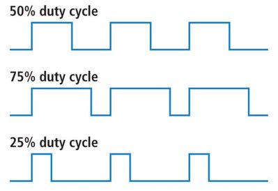
I pretty sure that pin 5 and 9 is a PWM-signal from the color misregistration sensor to the controller. It should give you a on/off alternating signal. Try to compare them. You should measure around 2.5V with a DC voltage meter if the duty cycle is around 50%. However, a oscilloscope would be better to verify this signal.

PWM.JPG


The DNSSR signal on pin 8 could mean something like "Density Secondary Right". The guess is based on pin 4 (DNSSL - Density Secondary Left) and pin 1 (DNSPL - Density Primary Left). I have no idea what this is. It could be another (Density) input to the controller. Try to compare the three signals.


Try also to read the eventlog by writing the IP-address in a webbrowser. Maybe the eventlog will tell more.


Good luck
-Jacob


HP Recommended

Hi Jacob,


Many Thanks for detailed info.


As your suggestions I have checked DC controller J111.  It is clearly the one that connects with colour plane registration (CPR) sensor. Without turning on I did test the J111. Pin 10 is GND and Pin 11 is +5 as per page 222. But I found they are shorting (pin 10 and 11) together with 6.5 Ohms. Then I removed all flat flex cables and tested still shorting. Then removed each cable for J108... to J101.  When J101 connects with it's cables connector J111 , pin 10 and Pin 11 shorts. 


Without connecting J101, Pin 10 and Pin 11 in J111 has 583.7 Ohms resistance between them. I think there should be no connection at all. Then I did test the Pin 1 (+5) of J101 with Pin 4,5,6 (GNDs). They also connects each other having 443.3 Ohms between them. I doubt there is kind of short between +5V and GND in DC controller board.


Will you be able to test J101 (pin 1 to pin 4,5,6) and J111 (Pin 10 to Pin 11) without connecting any cable to DC controller and let me know and connects just J101 and test Pin 10 and Pin 11 in J111.


Many Thanks for helpting me on this.


Thanks,


Regards,

Indi


Archived This topic has been archived. Information and links in this thread may no longer be available or relevant. If you have a question create a new topic by clicking here and select the appropriate board.
† The opinions expressed above are the personal opinions of the authors, not of HP. By using this site, you accept the <a href="https://www8.hp.com/us/en/terms-of-use.html" class="udrlinesmall">Terms of Use</a> and <a href="/t5/custom/page/page-id/hp.rulespage" class="udrlinesmall"> Rules of Participation</a>.